
The multi-mode microtube-electrospray propulsion system combines a catalytic chemical microtube propulsion system with an electric electrospray propulsion system. The system consists of one propellant tank, one set of feed lines/valves, one thruster that can be operated as high-thrust low-specific impulse chemical (180 sec Isp) or low-thrust high-specific impulse electric (>800 sec Isp) propulsion. It significantly expands the design space for satellites, while still fitting within the same mass/volume/power requirements. Perhaps most importantly it makes spacecraft flexible and adjustable, enabling the mission to be changed in real-time and enabling spacecraft to be quickly launched without a predetermined mission. My work with the MultiMode research team has focused on thermal design but branched to several other fields as well. All work was supervised by Professor Joshua Rovey.
Multi-Mode Microtube-Electrospray Propulsion
My Tasks
Lead Thermal Investigator
The goal of the thermal modeling is to explore the effects of geometry, material properties,and thermal interface resistance on the temporal evolution and equilibrium distribution of the temperature of the prototypical MMMP thruster. It is desirable to keep the manifold cool (<∼100◦C) to prevent propellant decomposition, while the micro-channel array is hot (∼150−200◦C) for propellant ignition and sustained combustion. The model presented in the upcoming conference paper explores how the manifold parameters will affect its equilibrium temperature.
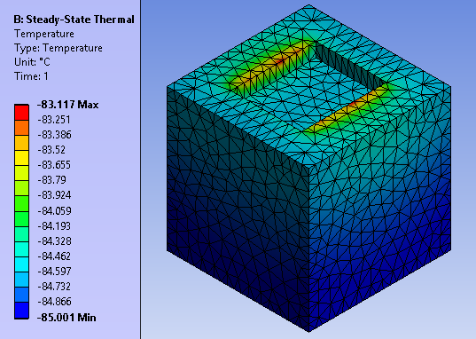
It was important to start with an analytical thermal analysis for comparisons with simulation data. The system was created and computed to show trends at varying thermal contact resistivity. After which, ANSYS Workbench was used to verify the analytical data. Once compared and verified, the simulations were then tasked with more intensive parameters such as varying materials, manifold sizes, and contact methods. Months of data was then compiled to find an optimal design for the assembly that meet the goal.
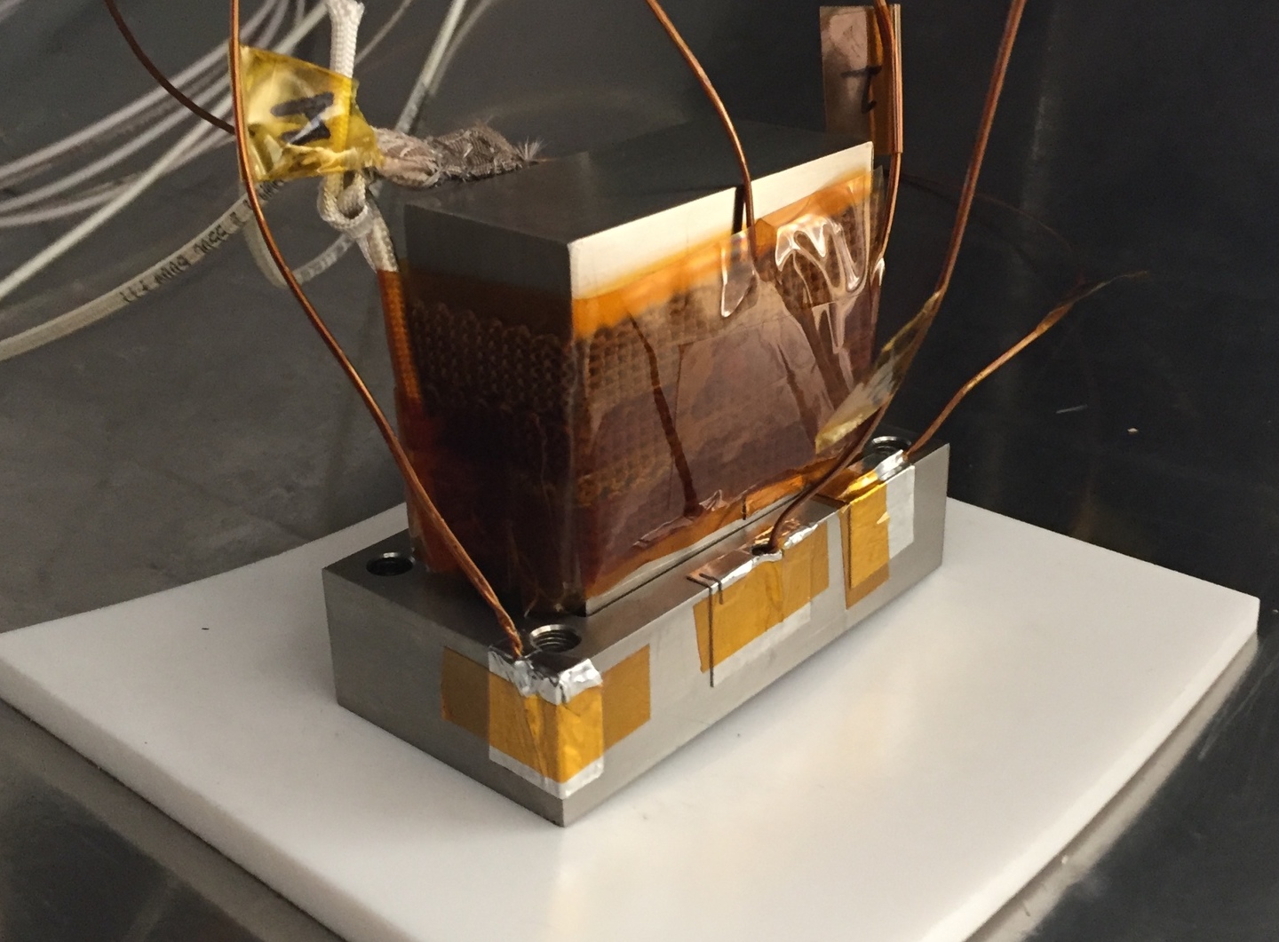
During this time, experimental test were conducted. Test were performed in the belljar vacuum facility. Temperature readings were collected using thermocouples attached to key points on the assembly. This data was collected over a span of 8 hours, or until steady state. The assembly was tested at varying array temperatures and compared with simulation data to determine the thermal contact resistivity. To collect data, LabVIEW was integrated with the oscilloscope to collect data twice every minute.
Electric Propulsion Facility - Vacuum Organizer
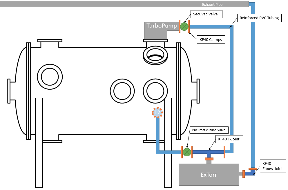
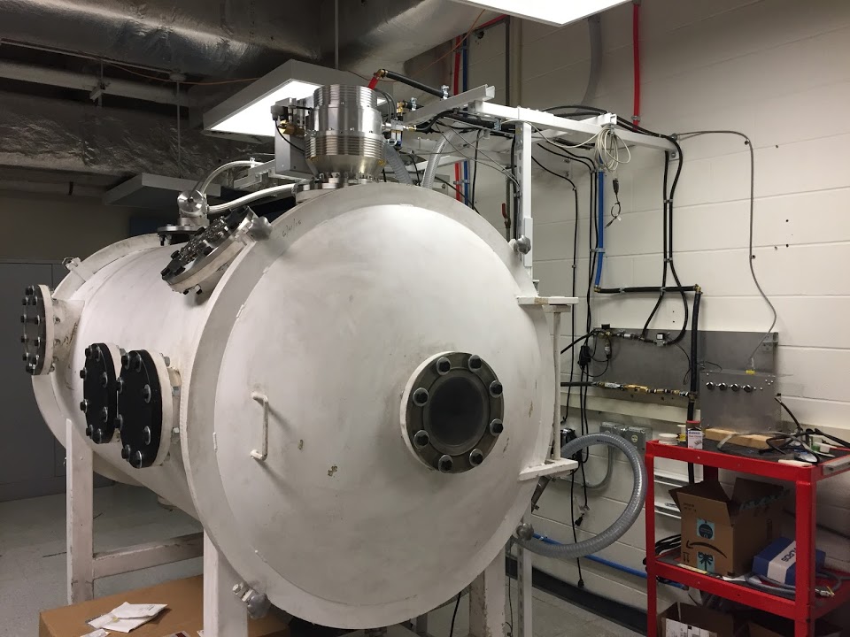
In the summer of 2018, I managed the construction of a new vacuum chamber facility to be used for Hall thruster experiments. This facility is 1.2-m-diameter and 2.1-m-long evacuated to a base pressure of 10-6 Torr. I organized, purchased, and managed the instruments and components necessary for the vacuum to operate. Equipped with 12 different ports, I focused on understanding what components were needed for each port and their specific need to the future research to be conducted.
Prior to taking this task, I had no knowledge of the complexities and challenges in the field of vacuum systems but gained it all in my five months it took to complete it. I gained an expertise of vacuum technologies from cryopanels, coldheads, turbo-pumps and rough pumps to vacuum standards like flange sizing and operation practices.
CNC Optical Channel Observer (COCO)
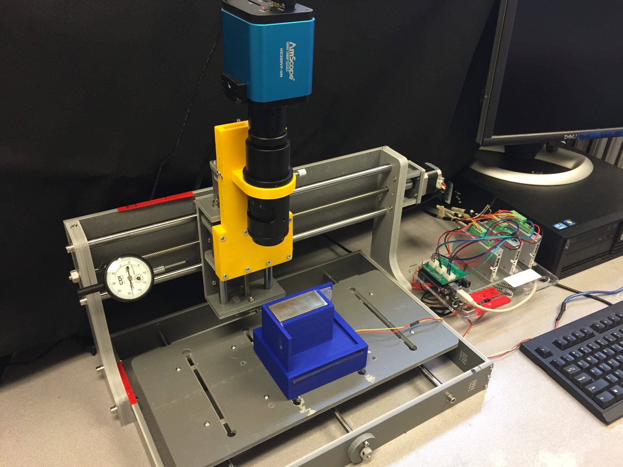
With multimode propulsion, a single thruster channel is roughly 10 micrometers in diameter and 6 centimeters long. To put it into perspective, the typical width of a human hair is between 60 and 80 microns. In order to bring multimode technology to a more applicable scale, a thruster array containing thousands of microchannels is needed. During the manufacturing process, the channels are etched into a stainless steel block, coated with a thin layer of platinum, and finally milled to create a nozzle. Throughout its development, the array is exposed to a number of factors that affect the integrity of the channels.
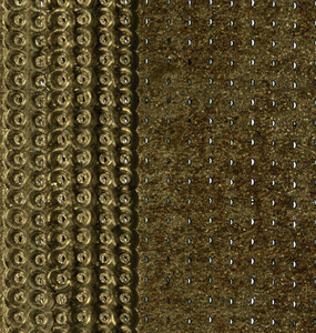
With an incredibly small system and complex manufacturing process, it is paramount that the surface of the array block be fully understood during each phase. Physical traits such as a channel’s absolute location, size, shape, blockage, and alignment with other channels must be understood. The system must be reliable and repeatable to allow for a channel by channel comparison of the thruster surface at different stages in the manufacturing process. COCO scans the array taking picture at one millimeter steps. These images are stitched to create a single panoramic image. Afterwhich, a neural network trained to detect channels, records data on the channel's location, brightness and shape.
To learn more about COCO, visit the GitHub Wiki.
Publications
Coming Soon!